The goal of this quick start article is to provide only the most relevant information for getting started quickly with Octane Standalone. For more detailed information, please reference the online documentation.
Interface Overview
Octane Standalone consists of four primary regions in the standard interface (Figure 01).
Render Viewport
A scene render is continually updated in the Render Viewport. The scene can be navigated in real-time. Adjustments to materials, lights and camera can be made and viewed interactively as well.
Node Inspector
The Node Inspector will display parameters related to specific nodes that are selected in the Node Graph Editor.
Node Graph Editor
All scene elements are represented by nodes in OctaneRender. The Node Graph Editor provides a visual, flowchart-like interface for managing these nodes.
Scene Outliner
The Scene Outliner provides an outline-like overview of all the elements in the scene. It also contains tabs for accessing the local and online material databases.
Figure 01: The four primary regions of the standard interface
Loading Scenes and Geometry
Demo scenes can be downloaded from the following location:
http://render.otoy.com/downloads/OctaneRender_1024_beta246_DemoSuite.zip
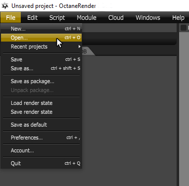
Scenes are loaded using File - Open (Figure 02). This method can be used to open the two native Octane Standalone formats, .ocs and .orbx.

Figure 02: Opening scene files in the .ocs or .orbx formats
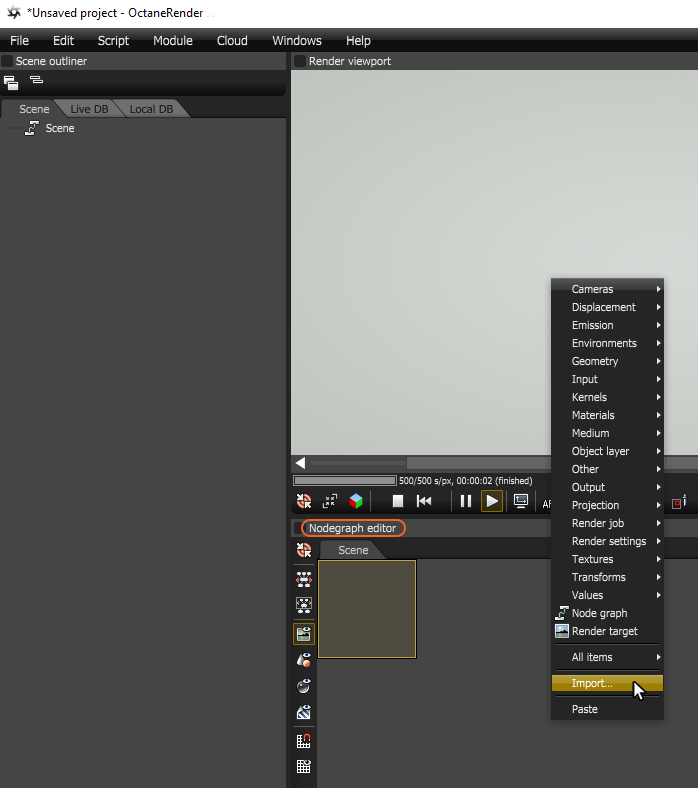
Geometry can be loaded using a number of methods, however, the simplest method is to right-click in the Nodegraph Editor and choose Import (Figure 03). This method will load many common formats including .abc (Alembic) and .obj as well as .ocs and .orbx.

Figure 03: Opening files using the Import option in the Nodegraph Editor.
Navigating Scenes
The following example uses the Screws scene provided in the Octane Standalone demo suite.
In order to activate the rendering of the scene in the Render Viewport, a Geometry or Render Target node needs to be selected in the Nodegraph Editor. In this example, the screws.obj Geometry node is selected. Additionally, the Render Geometry Nodes toggle must be activated in the left side-bar of the Nodegraph Editor (Figure 04).
Figure 04: Activating a rendering by selecting a geometry node and toggling on the Render Geometry Nodes button
Navigating in the Viewport
- Orbit: Left Mouse Button
- Zoom: Middle Mouse Button
- Pan: Right Mouse Button
Navigating in the Nodegraph Editor
- No orbit function since this window is not 3D
- Zoom: Scroll Wheel
- Pan: Middle or Right Mouse Button
There is an extensive set of buttons at the bottom of the Render Viewport window that are covered in greater in the User Guide. The Camera Focus Picker button is discussed here because it provides control over what area of a scene is in focus. Activate this button to sample an area of the scene in the Render Viewport that should be in focus (Figure 04a).
Figure 04a: When navigating a scene, desired areas of the scene may lose focus and the AF button can be used to sample an area and bring it back into focus
Using the Nodegraph Editor
It is important to control what is rendering in the render viewport. There are four buttons that provide this control. They can be found on the left side-bar in the Nodegraph Editor (Figure 05).
Toggles rendering of Render Target Nodes when selected in Nodegraph Editor
Toggles rendering of Geometry Nodes when selected in Nodegraph Editor
 Toggles rendering of Material Nodes when selected in Nodegraph Editor
 Toggles rendering of Texture Nodes when selected in Nodegraph Editor
Figure 05: The render toggles can be found on the left side-bar in the Nodegraph Editor
Working with Nodes in the Nodegraph Editor
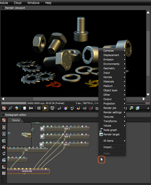
Nodes can be added to the Nodegraph Editor by right-clicking in the Scene workspace and choosing the appropriate node from the list (Figure 06).

Figure 06: Right-clicking in the Nodegraph Editor accesses the list of available nodes
Nodes can be linked together by dragging from an output pin on one node to the appropriate input pin on another node (Figure 07). Nodes can be disconnected by dragging the connection off of a pin.
Figure 07: The Light node's output pin is connected to the Geometry node's light input pin
Using the Node Inspector
The Node Inspector provides access to node parameters. The Node Inspector will display parameters for selected nodes in a scene (Figure 08).
Figure 08: A Diffuse material node is selected in the scene and its parameters are displayed in the Node Inspector
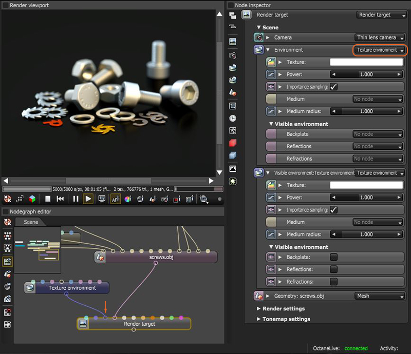
Many nodes will have an internal list of parameters available in the Node Inspector, however, they can accept inputs from other nodes to override their internal parameters. This provides a way to add more visual organization to parameters by leveraging the Nodegraph Editor (Figure 08a).

Figure 8a: A Texture Environment node is replacing the Render Target node's internal Environment parameters
There are a few specific node parameters that can be accessed in the Node Inspector without adding their corresponding nodes to the Nodegraph Editor. This allows for the editing of parameters crucial to the rendering process such as render resolution, camera location, and environment lighting without having to add nodes to the scene. These buttons can be found on the Node Inspector's left side-bar.
 Allows for the editing of parameters found in a Render Target Node
 Allows for the editing of parameters found in a Camera Node
 Allows for the editing of parameters found in an Environment Node
Note: When a actual Render Target, Camera, and/or Environment node is added to the scene, these default parameters will be overwritten and these buttons will access those specific nodes in the Nodegraph Editor.
Working with Cameras and Resolution
A default camera is always present in a scene. Controlling camera position and orientation can be accomplished with the three mouse buttons as described in the previous Navigating Scenes section.
Additionally, there are three types of camera nodes that can be added to the Nodegraph Editor. The primary camera node type is the Thin Lens Camera. Camera nodes are connected to the Camera input pin on a Render Target node (Figure 09). There can be multiple camera nodes present in the Nodegraph Editor thus allowing for multiple camera locations from which to render a scene.
Figure 09: A Thin Lens Camera node is connected to the Camera input pin on a Render Target node
Controlling Render Resolution
Render resolution is located in the Render Target node under the Render Settings rollout (Figure 09a).
Figure 09a: Selecting a Render Target node provides access to the Film Settings in the Node Inspector
Saving a Render
A static render can be saved by right-clicking in the Render Viewport and choosing the desired image format (Figure 10).
Figure 10: Right-clicking in the Render Viewport to save a rendered image
A render can also be saved by clicking on the Save Current Render button located in the bottom right of the Render Viewport window (Figure 11).
Figure 11: A render can be saved by clicking on the Save Current Render button
Additional Online Resources
- Online Documentation
- Tutorials
- Etc.