Mixing and Layering Systems in Octane: Standalone Stepthrough
This is meant to be a companion piece for Mixing and Layering Systems in Octane: Technical Deep Dive. Depending on how you learn best, you can either read that first and learn all about how each layering system works, then come back and do this stepthrough, or just dive right in and use that guide as reference
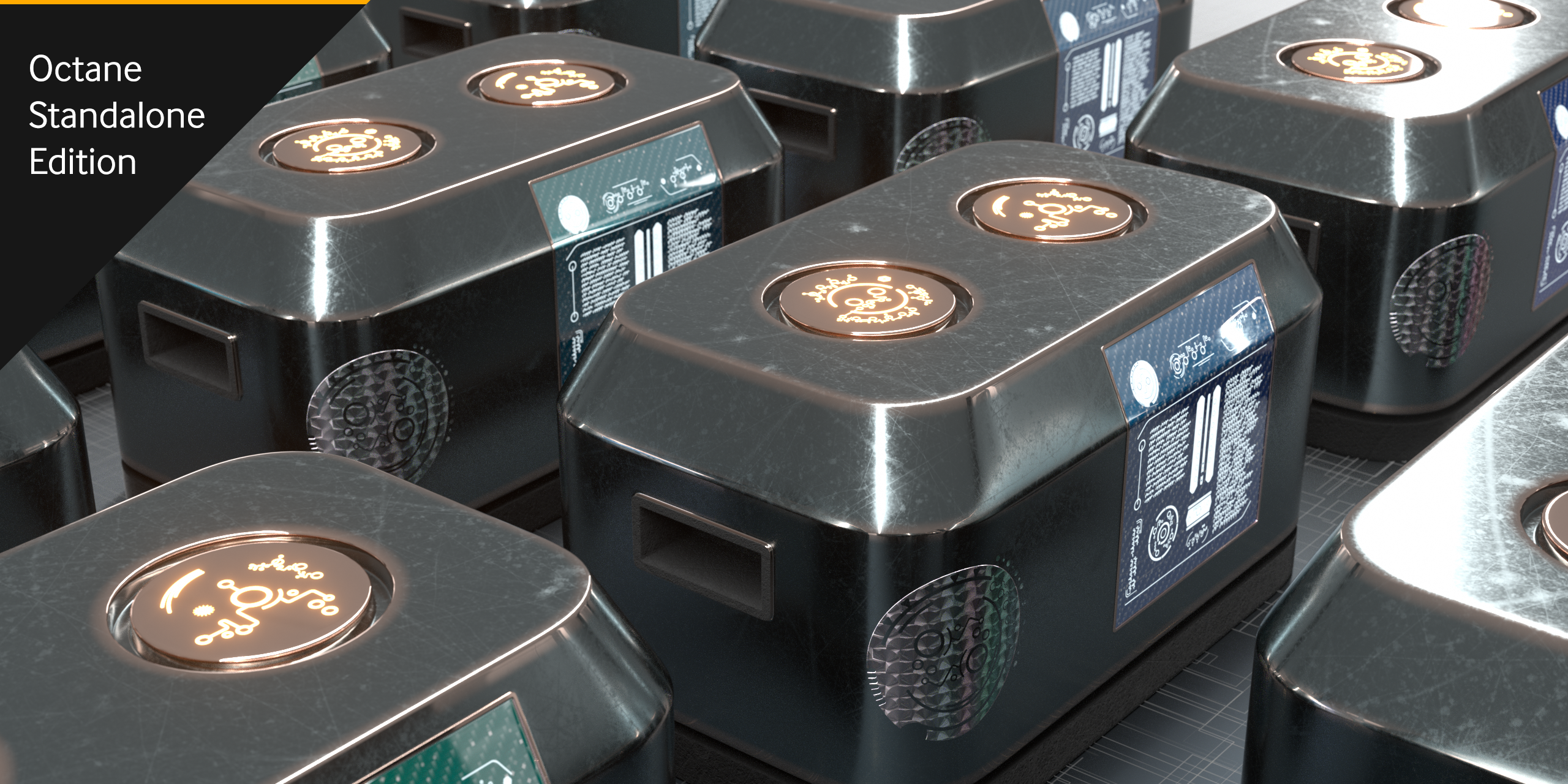
Octane has several ways of layering textures and materials together to form complex looks. This guide will walk you through how to use the most common ones by texturing a sci-fi crate.
Octane Standalone will be used here. Your DCC may vary a bit in how each of these systems are implemented, but the core concepts and parameters should be the same.
There is also a Cinema 4D-specific version of this document in case you’re using that.
Setup
We’ll need some assets to get started. These come from HDRI Haven, CC0 Textures, JSplacement, and the rest are custom assets built from scratch for this tutorial.
Geometry
For this exercise, we’re going to use a fairly simple sci-fi crate mesh. The mesh was intended to be subdivided. In Octane Standalone, in order to bring in an FBX, we’ll need a Scene Geometry Node. If we click the little wrench icon in the Node inspector, we get some options. In order to get the object subdivided, we need to enable “override file subdivision level” and “subdivide all meshes”, and then set the subdivision level to 3.
The scene has the Adams Place Bridge HDRI from hdrihaven.com (desaturated) for reflections, and the backplate is overridden by a neutral gray color so it’s not distracting.
Base texture
We’re going to start with a Universal Material. In Standalone, we’ll be able to feed this into a Composite Material later - in your DCC, you may have to take extra steps to convert materials into sub-materials before you can do this. If you’re using a DCC like Cinema 4D and know you’re going to be using a Composite Material, it’s often best to start with the Composite Material and just have the node create your sub-materials for you instead.
Setting up the Base Texture
Starting with the Albedo color, let’s go for a medium steel gray like #537297. Rather than set this in the material itself, let’s run an RGB color node in so we can swap it with something else later or mix it together if needed.
The other settings here are Metallic=1, Specular=0, BSDF Model=GGX (in case we want to do anisotropy), and everything else is default.
Building a Saw Wave Mask
Next up we’re going to add some scratches to this thing to rough it up and make it look used. This crate will probably see more damage on the sides and bottom than the top, so we’re going to use two different scratch maps. Both will get fed into the roughness channel, so this is a good place to use a Mix Texture node to tell Octane where to place each texture.
This is a pretty simple mask, so rather than worrying about masking out UVs or anything complex like that, we’re going to build a procedural setup that allows us to control the mask based on a gradient.
The Gradient node is one of those things that trips up beginning users of Octane. It doesn’t generate color data like one would expect coming from the 2D art world. It’s more like a remapping tool similar to a Levels or Colorizer effect. It needs a texture input to be able to do anything.
So what we’ll start with is a Saw Wave texture node. Saw Waves do generate color data, and rather than a Sine Wave that oscillates between 0 and 1 (white and black), a Saw Wave goes 0-1, then immediately starts over at 0, giving a great visual indicator of where the gradient starts and ends.
This node defaults to XYZ to UVW Projection, which is actually what we want. We’ll dive into this a bit later, but for now, it just means it will ignore the UVs and cover the whole model with the gradient.
Sidebar: Visualization
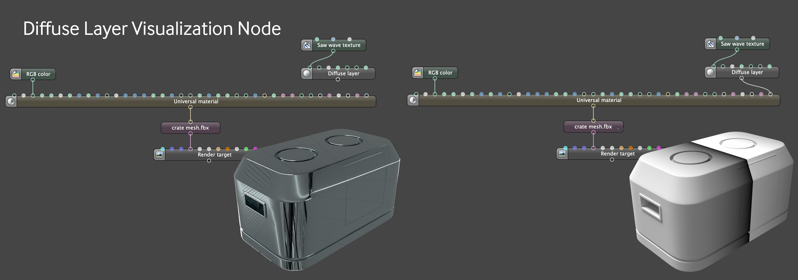
There are times where you’re going to want to isolate specific textures or effects on the model to make it easier to see what you’re doing as you adjust parameters. With the Material Layering system, this is as easy as dropping a Diffuse Layer in and hooking it up to the Material Layer input - this gives a blank canvas that you can try out specific nodes on by running them into the Diffuse Layer’s Diffuse channel input. When you’re done, you can just unhook the layer node and get back to your main material.
For more on the Material Layering system, check out the companion guide which goes into detail about how each of the layering systems in Octane work.
When we add the Saw Wave to our model, we’ll see that it’s going the wrong way. This is an easy enough fix, we just need to rotate the saw wave texture 90 degrees on Z in the Transformation section in the Node Inspector. Eventually you’ll get the hang of which way to rotate it, but for now, just type 90 or -90 into the various rotation parameters until it does what you want.
One thing about the Saw Wave is that sometimes the mapping to the object gets just a tiny bit off and you end up with some weird texturing error on the black or white end of the spectrum. This can be fixed by giving it a very tiny offset (0.001 worked in this case), or you can also scale it sometimes to fix that.
The Saw Wave gave us some color data to work with, but what it doesn’t give us is the ability to alter the gradient itself - this is where the Gradient node comes in. We’ll use that to remap the 0-1 values so we make kind of an elevation map, and then crush in the gradient knots to sharpen it up and mask out very defined areas. In this instance we’re leaving in a bit of the gray between the black and white to do a very quick blend between textures, but if we wanted a sharp line between black and white, we’d just need to set the gradient type to Constant instead of Linear. Again, this differs in the various DCC implementations - it usually depends on how the host app builds their gradients.
Mix Texture - Setup
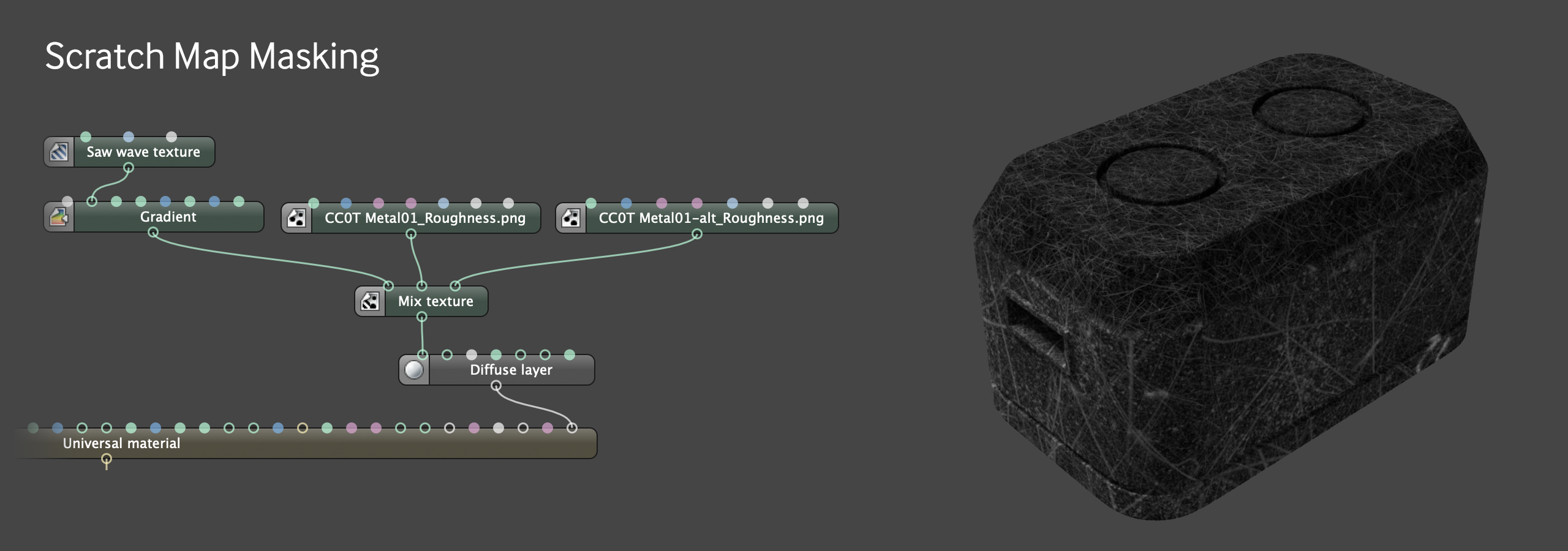
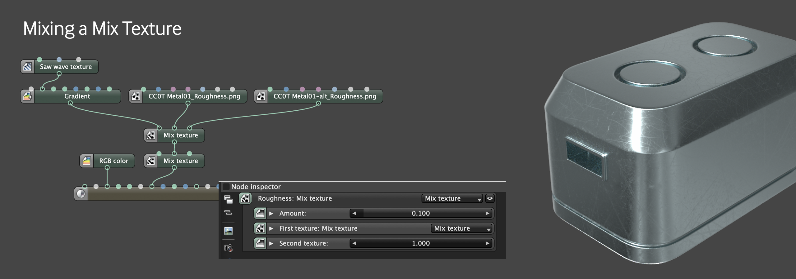
Now that we have our mask, we can use a Mix Texture node to put together our scratch maps. We’ll continue to do this on the Diffuse Material so we can easily see what’s happening, and then apply it to our Universal Material once we’re happy with how it looks.
Since both textures are grayscale and meant to go into the roughness channel, bringing them in as Grayscale Image nodes instead of RGB Image nodes makes more sense. Some DCCs don’t have a Grayscale Image node, so just use the Image Texture Node.
Input 1 gets the really rough scratch map so it looks like the sides took more of a beating than the top. Input 2 gets the less intense one, and then the mask that we made with the Sawtooth Wave Node which goes from black at the bottom (no contribution) to white at the top (full contribution) means that only the top bit gets the less intense scratching. The top texture needed to be scaled down a bit.
Mix Texture - Applying to Roughness
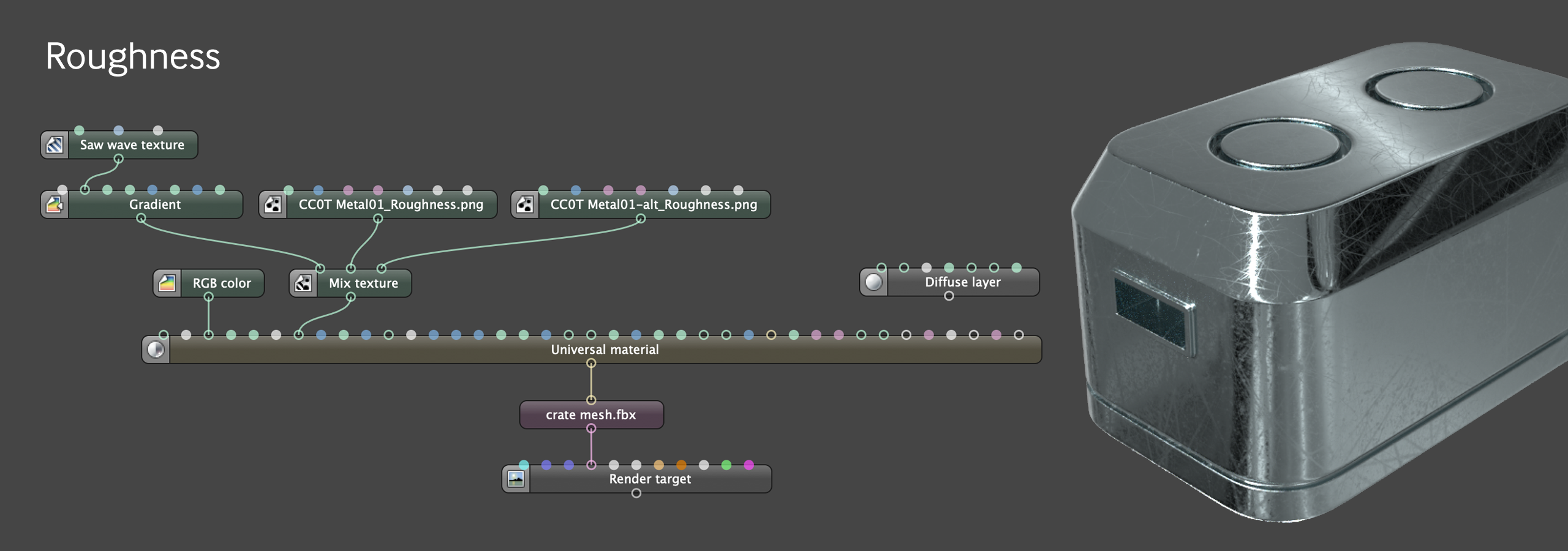
Let’s disconnect our Diffuse layer and pipe our Mix Texture into our roughness channel to see what it looks like. At any point, it might help to rotate the HDRI and/or increase the intensity to get a better idea of what it’s doing on a reflective surface.
Once the texture is applied to the roughness channel, it’s pretty obvious that 0.17 was a bit too small for the scale for the top texture. Play with the scale of each texture until it looks right.
The whole thing is still looking a bit shiny. Instead of going back and adjusting the textures, we can just run the whole Mix Texture node into another Mix Texture node and add a little white to it. Just brightening it up by .1 adds some roughness to the whole crate and makes it look better.
Edge Wear with a Material Layer
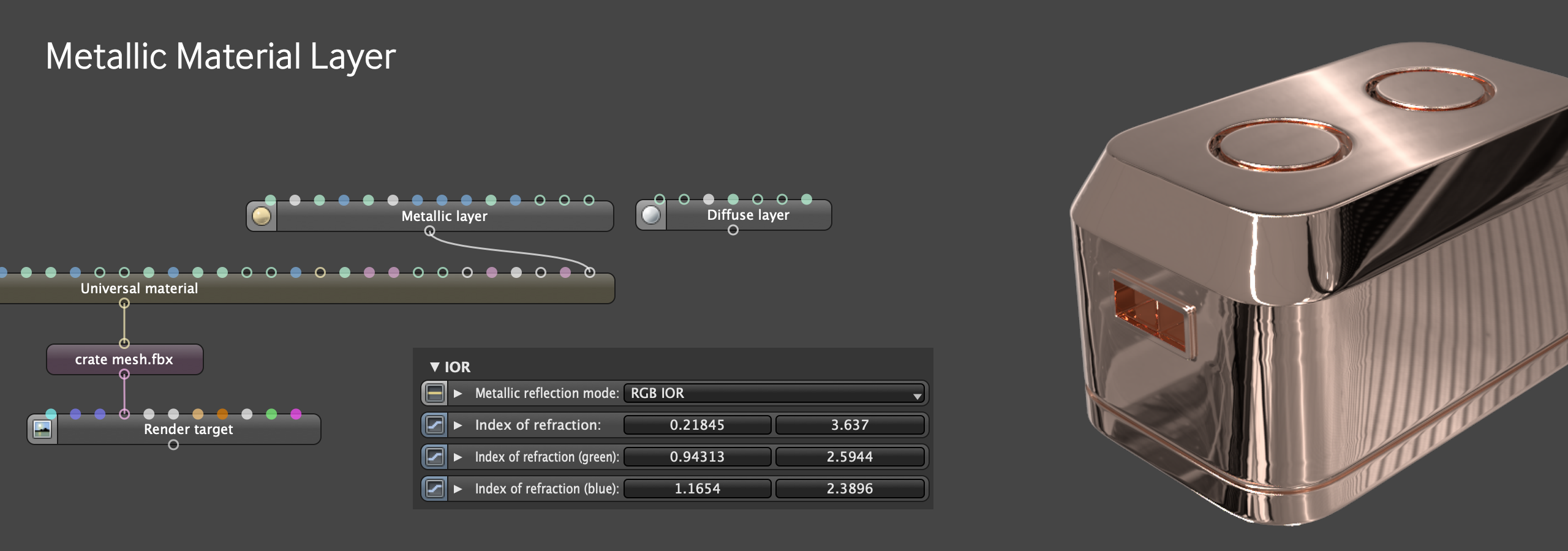
The last thing we’re going to do to the base material is add some wear. We’ll do this by adding a Metallic Material Layer and another mask into its Layer Opacity input.
First off, let’s make a Metallic Material Layer. In the Universal Material Guide, we show you how to change the metallic IOR to get realistic metals. We’re going to go for a copper here because hey, why not.
We’re going to keep the Diffuse Material layer there - hanging out in space not connected to anything - because we’ll need it in the next step to make the mask.
Dirt Node Mask
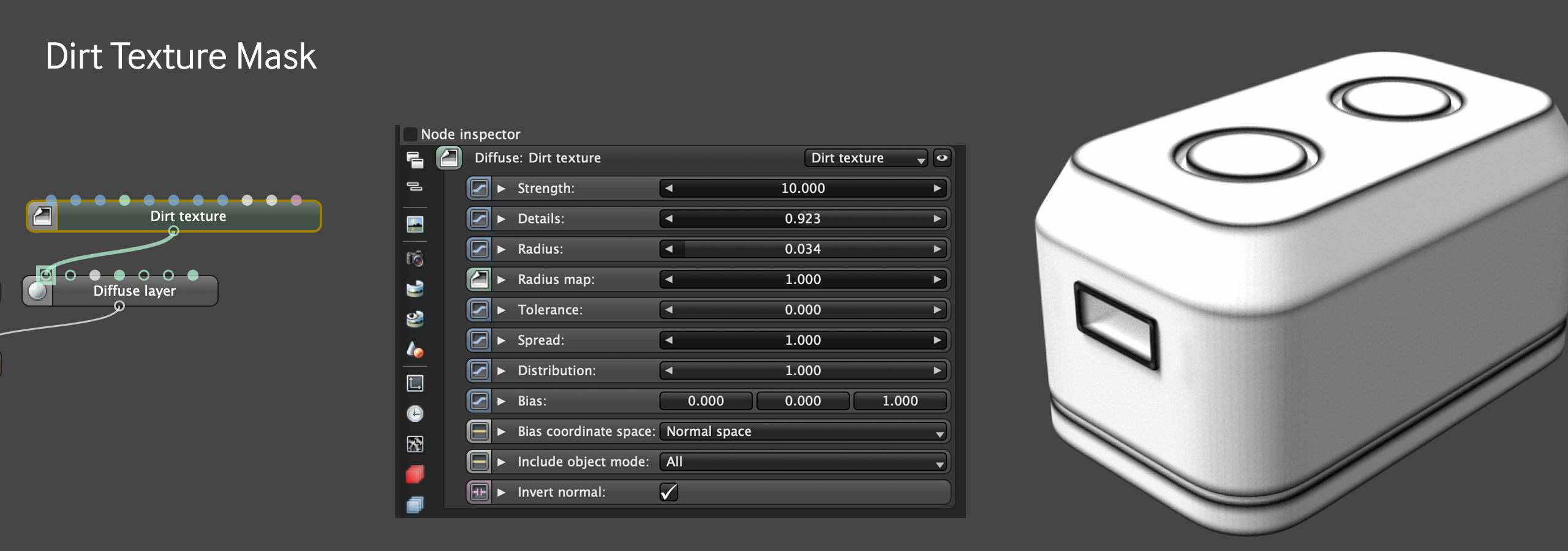
Time to make the mask for the copper wear. The Dirt Texture node allows you to find the edges of a model. Let’s hook that Diffuse Material Layer back up and apply a Dirt Texture node. There are a bunch of parameters to play with here, but the most important one for a mask like this is “Invert Normals”. Once that’s checked, play with the Radius, Strength, Spread, Details and Bias to get the Mask looking how you want.
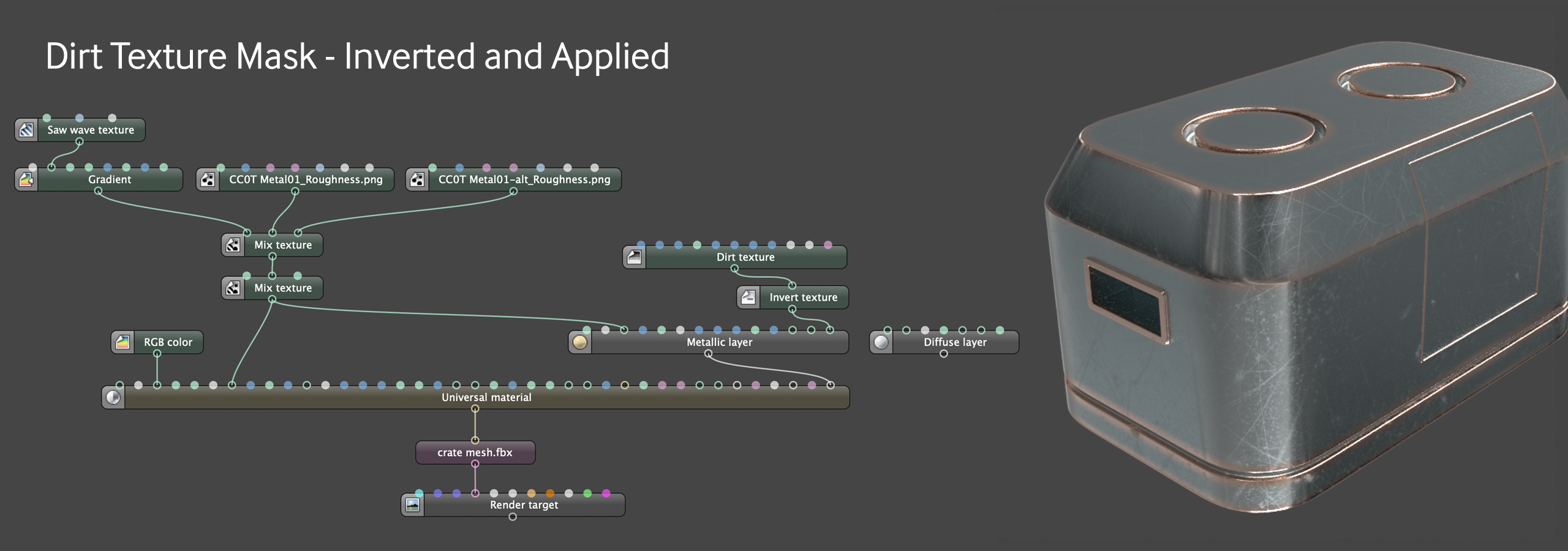
Since this is a mask for the copper layer, the white shows where the copper will be. We want the opposite of this - the copper should appear on the worn edges, so we’ll need to invert the mask. Pretty easy to do - just run it through an Invert Texture node.
There’s a ton more we can do here like rough up the dirt node with a noise and a mix texture, but for the sake of expediency, we’re just going to leave it alone and move on.
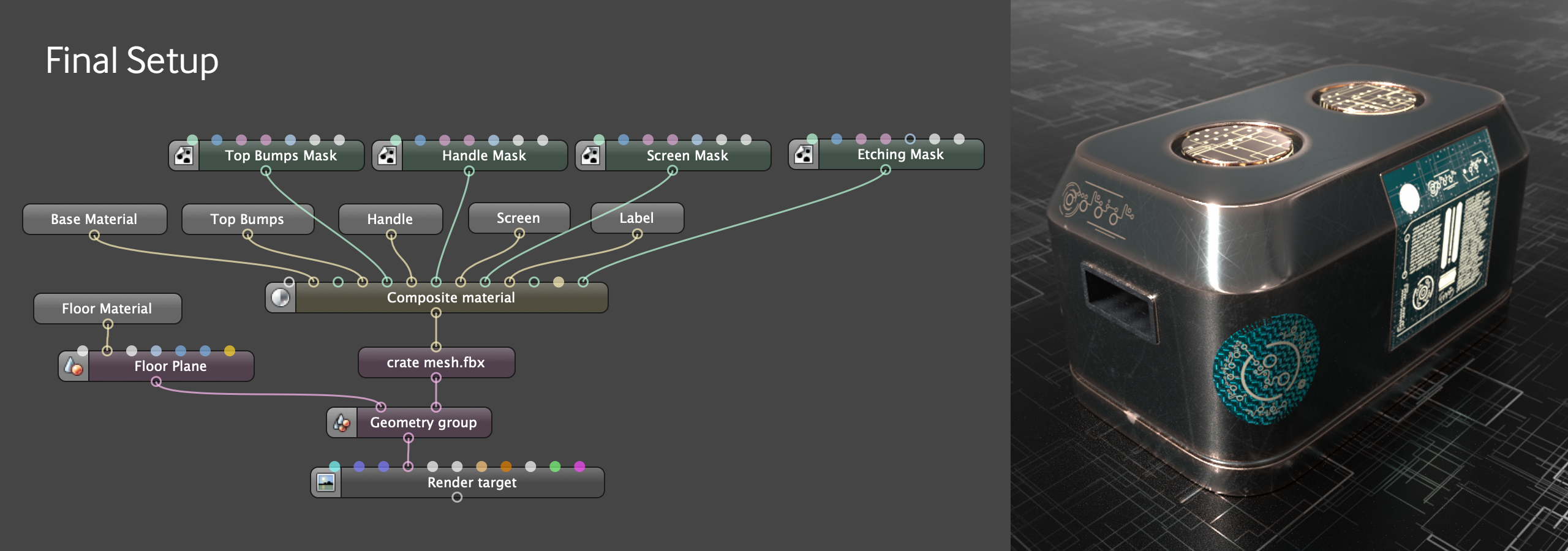
Composite Material
Now we want to add a separate material for the handle, screen, bumps on top, and maybe a couple of labels for good measure. It’s possible to do all of this in the base material using a Material Layer Group and a bunch of extra Material Layers, but then it becomes a little more cumbersome in the Nodegraph Editor and a little more difficult to reuse the components. A Composite Material allows this whole setup to be very modular.
Grouping the Base Material
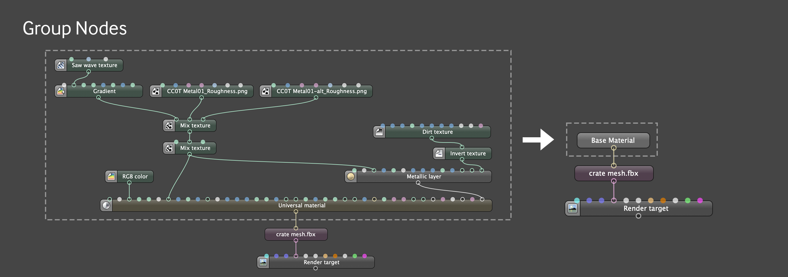
In Octane Standalone, grouping a set of nodes (select the nodes, right-click one of them, Group Items) allows for a very clean Nodegraph Editor. The different DCC plugins handle this differently - some don’t support grouping, and extra steps are sometimes needed to convert a regular material into a submaterial to feed into the Composite Material. It’s worth checking the manual of your DCC plugin to see how this works. We’re going to group each material as we go and rename each group so it’s easy to go back and edit later.
Getting the Masks Ready
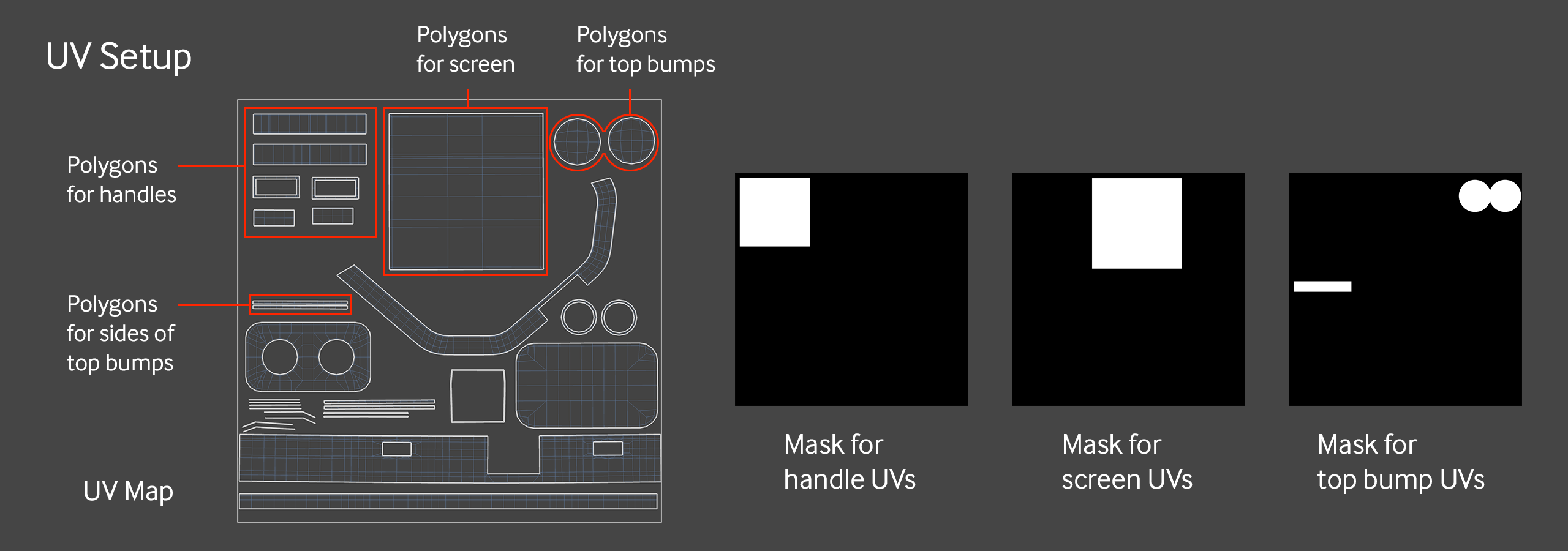
The UV set for the crate model is pretty decent, and has very distinct areas for the handles, top bumps, and screen (almost like it was made for this tutorial or something!). When making masks based on UV maps, the areas you want to mask out can be very rough as long as they don’t overlap UVs that correspond to other parts of the model.
In the model we’re dealing with, all of the handle polygons will get the same texture, but since they’re all grouped in the upper left corner and not packed in tightly with other polygons, a single, loose rectangle mask will work fine for this.
Same thing with the mask for the screen - it just needs to fully cover all the UVs meant for the screen, and can overlap into the area with no other UVs without issue.
The UVs for the top bumps are split across two parts of the map. So long as both areas are represented as white, the same texture or material will be applied to both parts of the model.
Let’s check out how this works for the top bumps portion
Top Bumps Material
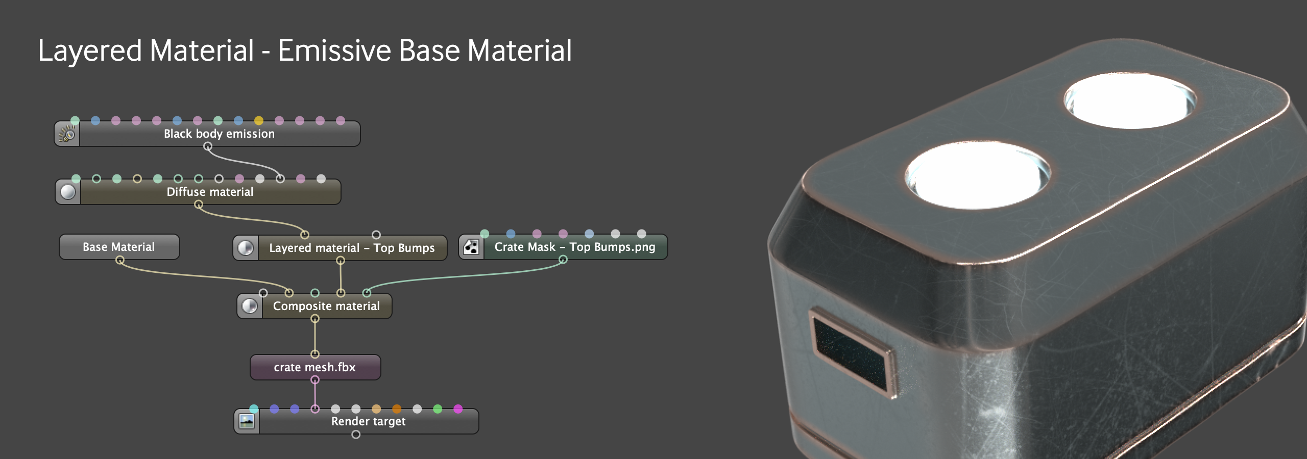
What would be cool here is a copper material that has some emissive rivulets and dots embedded in it. As usual, there are several ways to go about this. Since we have our copper as a Material Layer already from the edge wear part of the base material, Let’s use a Layered Material here so we can reuse that.
As we know, we can’t make a Material Layer emissive, so if we want emission (and we do), we’ll need to put that in the Base Material. To keep it simple, for the emissive part, we’re just going to make a Diffuse Material and feed a Blackbody Emission with a Power of 300 into it. That goes right into the Base Material input.
This whole Layered Material will be constrained to just the Top Bumps portion, so we can use one of our UV masks in the main Composite Material to mask that off. The emissive material is going into the Material 2 input of the Composite material, so that means our mask must go into the Material 2 Mask input.
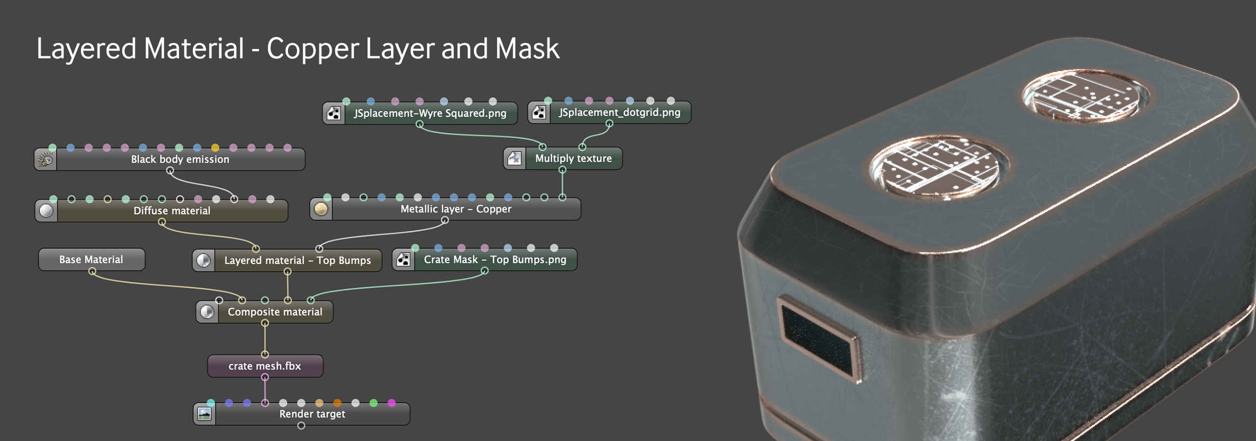
Now it’s time to overlay the copper and mask that out so only small portions of the emission come through. We can dig into our Base Material group (double-click it), grab the copper Material Layer, then come back out (click the tab for the main material) to get to the main node graph and paste it in.
For the Mask, we’re going to combine two JSplacement png files using a Multiply Node and feed this combined texture into the Layer Opacity for the Metallic Layer. We’ll notice it looks off at this point because of the way the textures are set up - right now the bumps are mostly emissive, with just slivers of copper going through. We want the inverse of this.
We can either run the whole thing through an Invert node, or go into the nodes for the textures and choose “invert” - that’s usually the easier way to do it.
At this point you can just scale and move the textures around until they look good.
Let’s collapse this material up and move on.
Handle Material
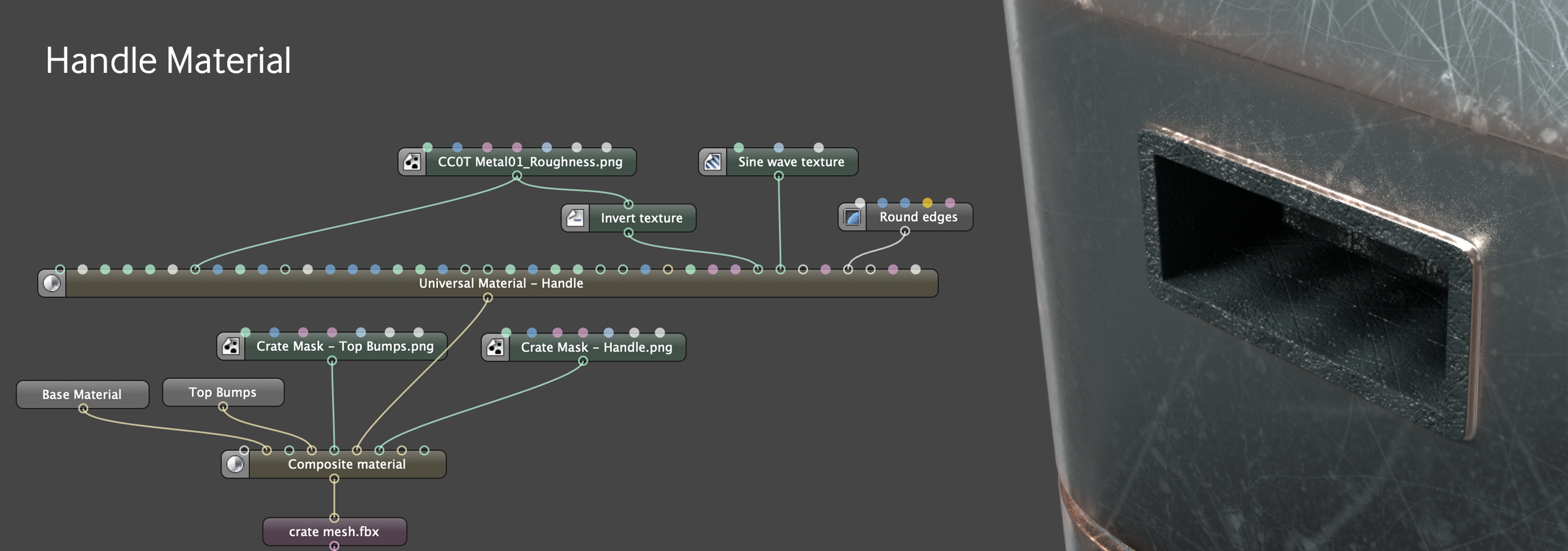
The handle material is pretty simple - just a matte Universal material with the same roughness texture we used for the base material in the roughness channel, and then inverted and placed in the bump channel so it feels like gouges rather than welts. There’s a Sine Wave texture going into the Normals to give it a little variety and a Round Edges node to take a little of the sharpness away and make it feel a little more plasticky.
We’re not doing any mixing here, so we’re not going to spend more time on it. Let’s feed this into the Material 3 input of the composite material, and put the Handles UV mask into Material 3 Mask input, Wrap the handle material up in a group, and move on.
Screen - Readout Placement
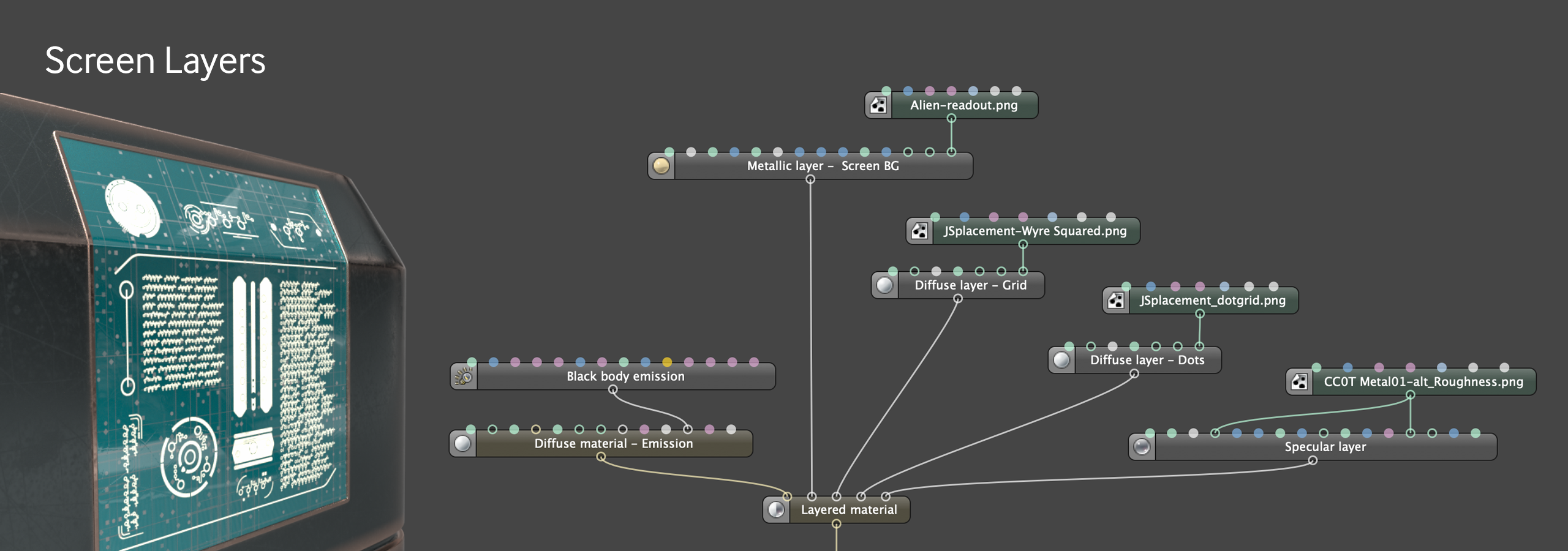
For the screen, we’ll use another Layered Material.
We’re going to do the same thing we did for the top bumps and put down an emission base layer (since we can’t add emission as a Material Layer), and then mask it off with the next layer up, which is the panel readout texture.
When we were doing the top bumps, we just dropped the texture in and masked it off to just the polygons we wanted. It didn’t really matter where the texture landed on the map since it covers the whole thing, and just repeats if we shrink it.
For this readout, it suddenly becomes important where the texture actually sits in relation to the map.
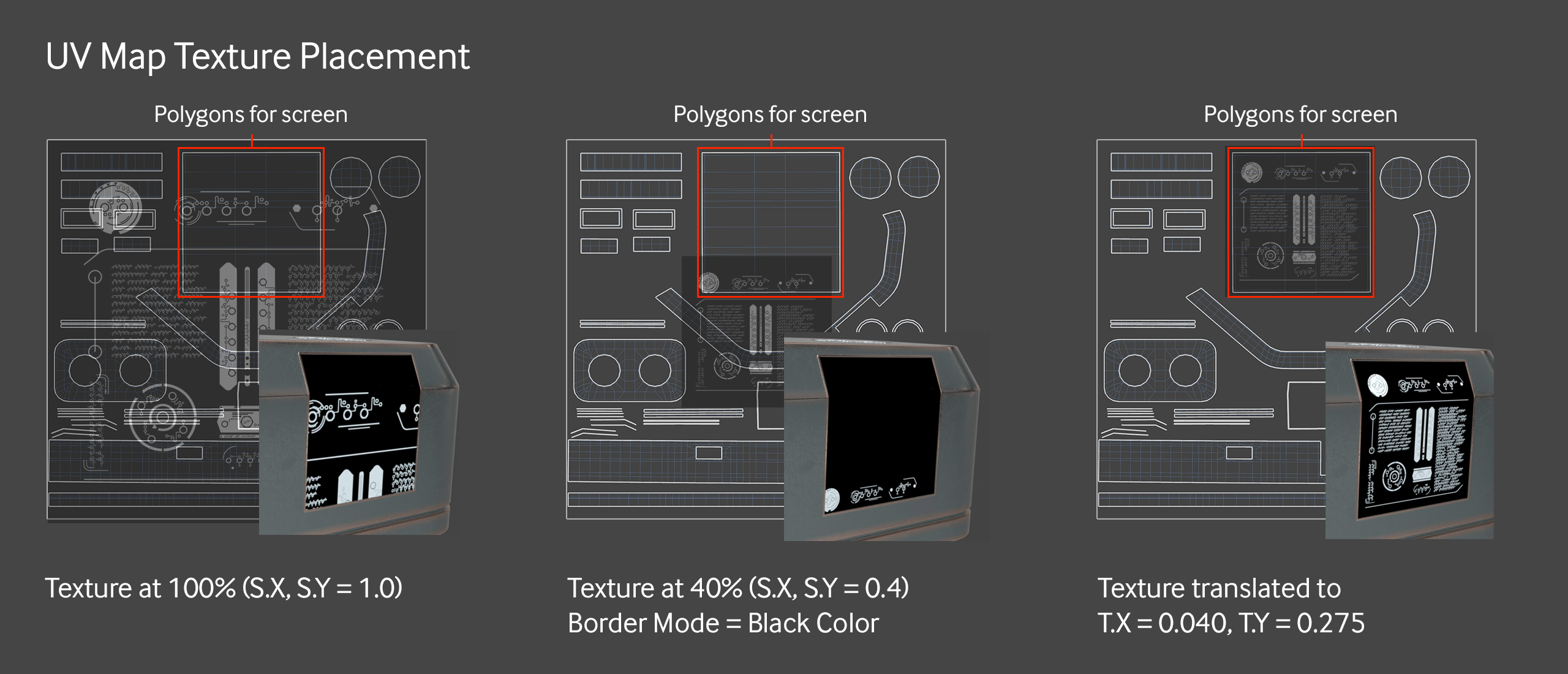
The Border Mode for the readout texture needs to be set to black - that means it fills the rest of the pixels with a black color (no contribution) rather than repeat the image. This will make the placement easier and avoid unwanted artifacts due to the texture repeating.
After that, we just need to scale it down (0.4 worked here), and move it around on the UV map until it’s placed properly. To sit nicely in the area designated for the screen, it needed to move a little bit over in T.X to 0.040, and a quite a bit up in T.Y to 0.275.
Most of the time you can just eyeball this by pushing the numbers around, but if you have a view of your UV map, you can estimate where you need your texture to be by thinking of 0,0 as the center of the UV map. The center point of your texture can move up to 0.5 in any direction (more than that will loop it around and be really hard to visualize). So if you need it in the bottom left corner of the map, you can start moving your T.X and T.Y values toward -0.5 and -0.5, and then fine-tune it as you start to see the image appear on the correct polygons.
Alternatively, if you have the UV map handy as an image, you can custom-build your texture in a 2D editing app to fit exactly where you want it, and then you don’t have to worry about scaling or moving around. The downside is that the texture isn’t really as reusable anymore.
Screen - Other Layers
Now that we’re happy with the placement of the mask, we can stack on a couple of other background texture layers for variety, and then coat the whole thing with a Specular layer to make it glassy. A lot of this could be achieved just within a Universal Material, but the more complex it gets, the more custom masking needs to happen and the harder it is to tweak things, whereas with a Layered Material you’re a lot more free to move things around in groups and experiment without having to do a lot of node trickery.
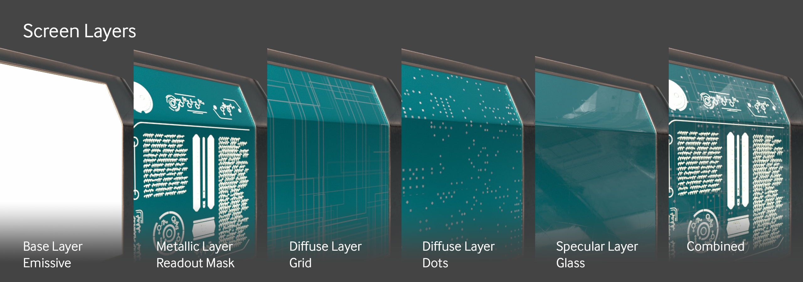
The Screen texture gets fed into the Material 4 input of the Composite Material and the Screen UV mask gets put into the Material 4 Mask input. Group and rename the screen material, and we’re ready to go to the next part.
Label
For the label, we’re going to go for a different approach to the masking. We don’t have a custom UV mask, and actually we’re not even 100% sure where we want it to sit. In this case, it’d be better to keep the label more modular so we can move it around on the UV Map.
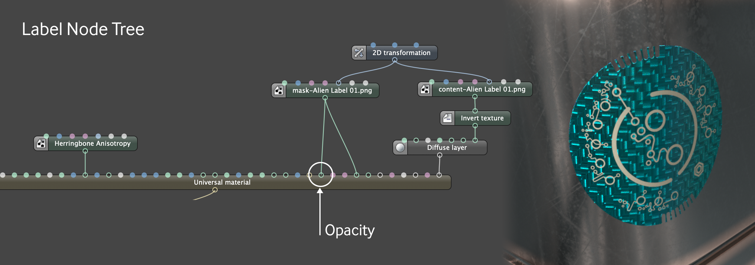
For this to work, we need to make the edges of our label material transparent before it gets fed into the Composite Material. We can use a Universal Material for the label and feed the label mask texture into the Universal Material’s Opacity channel. The Universal Material will just work like a sticker we can put anywhere on the UV map (or we could even use a different projection if we wanted).
Another thing of note here - the label is in two parts - the base - which we have as a metallic material with anisotropy and all handled in the Universal Material - and the text which is a Diffuse Layer on top. Both of these layers need to move and rotate together, so we need to use an external 2D transformation node to control them both at the same time.
The label is scaled down to 0.08 and moved -0.017 on X and -0.346 on Y to land on the polygons that wrap around the front corner of the crate. It’s also rotated 120 degrees because it looks better that way.
This whole material gets fed into the Material 5 input of the main Composite Material, and then grouped and renamed. No need for a Material 5 mask this time because the label was made transparent before piping it in.
Etching
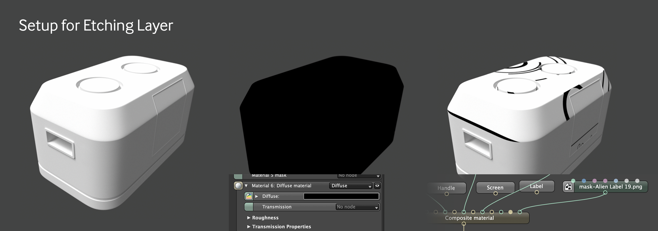
For the final detail, we’re going to make a quick and dirty mask for the etching that doesn’t rely on UVs. We’ll just project it right on the side of the crate.
Setup
This is going to be easier to visualize if we unhook all the layers we currently have so we once again have a white white crate to look at.
Now we need a material to mask out. This is the super lazy way, so rather than make a new material and pipe it into Material 6, we’re going to just go into the Node Inspector for the Composite material and tell it to make one internally by choosing Diffuse Material in the Material 6 area, then change the diffuse color to black. The whole crate should turn black.
Now we need a texture for the mask - we can use the included Mask Alien Label 19.png and bring it in as a greyscale texture node (or Image Texture node or whatever your DCC uses to import textures). We don’t want it repeating everywhere, so let’s set the Border Mode to Black Color. Let’s run that texture into the Material 6 Mask input of the Composite Material. This masks off a portion, but it’s the wrong portion.
Projection
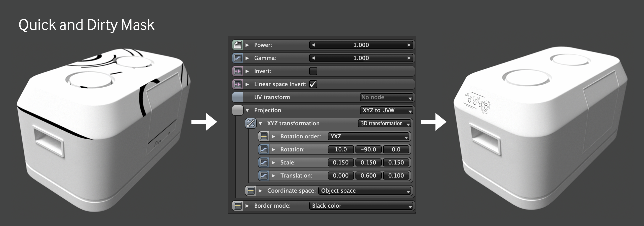
Way back in the beginning, we used the XYZ to UVW Projection for our Saw Wave mask. We didn’t have to do anything special because the Saw Wave node defaults to that projection type. When an image texture is brought in, it defaults to Mesh UV, so that needs to be changed if a different projection is desired.
Let’s go ahead and change that to XYZ to UVW in the node inspector. This immediately changes the look of the texture. It’s now relying on the object’s local XYZ coordinates for placement rather than the UV set. When moving textures around in the UV space, we only had to worry about two dimensions since the UVW mapping did the 3D projection for us. In XYZ to UVW projection, we need to tell it which way to project from, so we need control in 3 dimensions.
In our UV masks, we used the UV transform node (internally or externally). For XYZ to UVW projection, the 3D transformation node is more useful since we’ll need to adjust the projection in 3D space.
Most of the time this is just going to be messing with values until it looks right, but the first thing you usually want to do is figure out which side of the model you want to project on. For this crate, it defaulted to the side with the screen. We want it on the side with the handle, so let’s rotate it -90 degrees on Y. I know this because I first rotated it +90 degrees and couldn’t see it, so I changed it to -90 and it showed up on the side I wanted it on.
The angle of that bevel is... eh.. idk, 10 degrees? sure, let’s rotate it 10 degrees on X - it just needs to not look too distorted. It doesn’t need to be rotated on Z.
From there it’s a matter of scaling it down and pushing it around in Y and Z in the translation values until it appears where we want. Great, now we hook up the rest of the layers again, change the material to a copper, or just change the internal diffuse material to a coppery color like #D0B6A1 if we’re lazy, and there we go - instant etching.
Final Touches
A floor with a material was added to give the crate something to sit on - it’s just a simple geometric plane and the material reuses one of the JSPlacement textures we already have.
A little depth of field here, a little bloom and glare there... and it’s ready to ship some alien artifacts across the galaxy.
